Technical info
What you should know before issuing a request for proposals: the range of the radio link, how many receivers are needed per floor, the system's limitations, and which devices operate on solar power, batteries, or an AC adapter.
Coverage and Antenna Planning
Based on a conservative estimate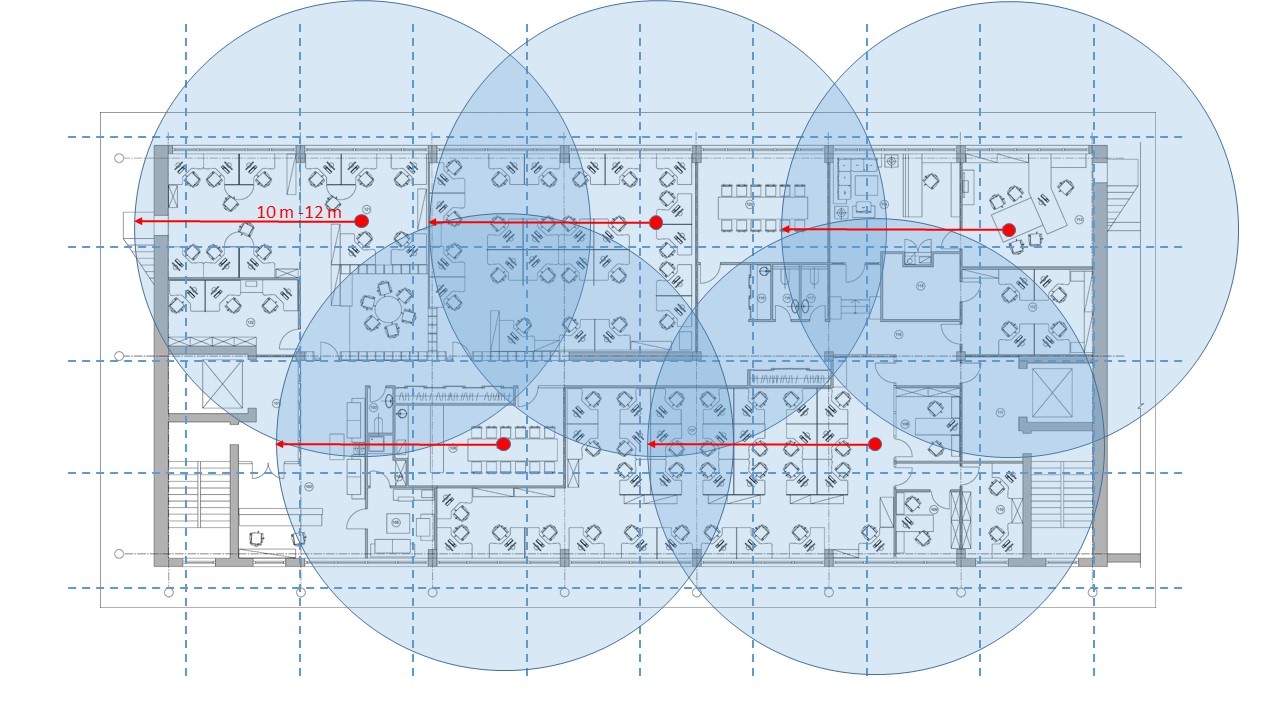 Example, not a guideline: For this floor, there are five receivers—one above and one below the center aisle—excluding the left stairwell. A different floor will yield a different number.
With a design radius of about 12 m, one EnoDisc® covers approximately 450 m². This figure is a design estimate, not a measured value: The actual range of a radio signal depends on the building’s structure.
Solid walls along a central aisle, elevator shafts, and firewalls significantly attenuate the signal. That is why we plan to place receivers on both sides of the aisle instead of using a central antenna. In practice, fewer receivers are often needed than a conservative plan would suggest.
You do not need to calibrate the sensor itself: It reports to the next available receiver, and multiple receivers may receive the same telegram.
EnoDisc® in Detail →- About 450 m² per receiver on open land.
- With a lot of drywall, it tends to be more; with concrete and shaft walls, it tends to be less.
- Applies to the floor shown above; this is not intended as a general guideline for an office floor.
- Calculated conservatively, without knowing the eventual layout.
- Consider stairwells and ancillary areas separately.
- EnoDisc® connects via Power over Ethernet; a single cable is all that's needed.
- There are no wires connected to the sensors themselves.
From Floor Plan to Number of Devices
Step 1 of 6Consider the usable floor area. Stairwells, utility rooms, and underground parking garages are excluded for now; they will be included in step four.
Where the System Reaches Its Limits
Figures for the Request for ProposalsHow many gateways do I need?
Calculated, not estimatedHere is a brief summary of the calculation above, so you can verify it using your own numbers. The answer is generally: one gateway per floor. This is our planning recommendation, not the technical limit—one gateway supports up to 32 receivers and 500 sensors, which, mathematically speaking, covers several floors.
We still recommend it on a per-floor basis for four reasons: Each floor can be configured as a self-contained unit, it operates independently at , maintenance remains localized, and a malfunction affects only one floor instead of half the building. In addition, there is the planning flexibility: Retrofitting can be done later without a new gateway.
Example of an office building with eight floors, each approximately 1,000 square meters: Four receivers and 40 sensors per floor— , that’s eight gateways for eight floors. Each is then assigned four of the 32 receivers and 40 of the 500 sensors. Mathematically, just one would have sufficed, because 32 receivers and 320 sensors fit exactly within the limits—but then the entire building would depend on a single device, with no backup. In detail:
| Per floor | 4 EnoDisc®, 40 sensors |
| Recommendation | One gateway per floor, i.e., eight for eight floors |
| Utilization per gateway | 4 out of 32 receivers, 40 out of 500 sensors |
| Limit per gateway | 32 receivers, 500 sensors—a limit, not a planning target |
| When Less Is More | A gateway can consolidate small areas with few devices . Technically possible, but inconvenient to maintain . |
- Determine the receiver's location based on the area; , guideline: 12-meter radius per EnoDisc®.
- Install one gateway per floor; do not push the limits of the .
- Verify that no floor has more than 32 receivers or 500 sensors.
- Leave the spare in place intentionally, for retrofitting with the " " during operation.
Stairwells, utility rooms, and underground parking garages are considered separately. Send us the floor plan, and we’ll calculate it for your building.
Solar cell, battery, or power supply
16 Devices at a Glance| Device | Solar cell | Battery | Power supply |
|---|---|---|---|
| EnoSense® Temp/RH | – | CR1632 | – |
| EnoSense® Desk | – | CR1632 | – |
| EnoSense® Desk VIB | – | CR2032 | – |
| EnoSense® Wall + Desk | Yes | CR2032 | – |
| EnoSense® LUX | – | CR1632 | – |
| EnoSense® PIR DOT | – | CR3032 | – |
| EnoSense® PIR Ceiling | Yes | CR2032 | – |
| EnoSense® People Counter | – | 2 x AAA | – |
| EnoSense® Presence Count | – | – | 12–60 V DC, PoE, or USB-C |
| EnoSense® CO2 | Yes | 2 x AAA | – |
| EnoSense® NOISE | Yes | 2 x AAA | – |
| EnoSense® PM VOC | – | – | 12 V DC |
| EnoSense® RADON | – | – | 12 V DC or PoE |
| EnoPuck® CO2 | – | – | 12 V DC |
| EnoPuck® CO2 WALL | – | – | 12 V DC |
| EnoPuck® CO2 NOISE | – | – | 12 V DC |
It doesn't always work without a battery
All sensors operate using the EnOcean wireless standard, but not all of them can function without a battery. In these cases, solar-only operation is not technically feasible or is not energy-efficient:
- Rooms with automated lighting switch-off
- Rooms without windows, such as prayer rooms or quiet rooms
- Workplaces where objects regularly cover the solar cell
- Regions with limited daylight at times
- Parameters with high energy requirements, such as VOCs
Whenever a battery is required, we make sure to use readily available standard cells that can be replaced without tools. In the EnoSense® CO2, for example, two AAA batteries are located behind the housing cap.
How often a sensor transmits
This determines the power consumption and, consequently, the power supply. The interval at which a sensor transmits is set for each device. The reporting frequency—often called the transmission interval—is thus set: A signal is transmitted whenever the measured value changes—and additionally as a “sign of life,” even if nothing has changed. The device then repeats its last value, typically at least every twelve hours, depending on the type. This ensures that a malfunctioning device is detected even when the room is not in use. Depending on the type, this interval can be as short as a few minutes—the radon sensor, for example, transmits only every few minutes because its measured value changes slowly. The transmission interval for each individual device is specified in its data sheet.
Filter all sensors with power supply →Installation Location and Installation Height
Per device, in one locationThe height at which a device is mounted determines what it measures. The short answer: Air sensors for CO2, temperature, and humidity are mounted at heights of 1.1 to 1.7 m ; motion detectors are mounted on the ceiling at 2.5 m; the People Counter is mounted above the walkway at 2.2 to 2.5 m; the Presence Count is mounted at 4 m; and table sensors are placed on or under the tabletop. The details and the rationale are provided in a separate article, device by device; the heights are taken from the data sheets, the model floor, and—where certification applies—from WELL itself.
The specification “1.1 to 1.7 m” is the WELL v2 requirement for measuring devices and displays. RESET Air permits a range of 0.9 to 1.8 m and additionally requires a minimum distance of 5 m from windows that can be opened and supply air vents. Without certification, the breathing zone is generally considered to be 1.2 to 1.8 m.
Radio Standard and Alliance
Step 1 of 3Where Interoperability Comes From: A Standard, an Association, and the Question of Who Manufactured the Device.
Compliance and Approvals
What the statement saysOur devices bear the CE mark in accordance with the Radio Equipment Directive 2014/53/EU and comply with the substance restrictions set forth in Directive 2011/65/EU, as amended by Delegated Directive 2015/863/EU —commonly referred to as RoHS 3. Both are specifically listed in the Declaration of Conformity for the respective device.
The CE Declaration does not apply outside the European Union. Radio communications are regulated at the national level, and each frequency variant therefore has its own national certification. The determining factor is not the customer’s place of business, but the location where the system is operated.
Statements and Certificates in the Download Center →| Frequency | Market | Approval |
|---|---|---|
| 868.3 MHz | European Union | CE |
| 868.3 MHz | China, Singapore | CCC, IMDA |
| 902 MHz | North America | FCC |
| 902 MHz | Colombia | CRC |
| 921 MHz | Taiwan, South Korea | NCC, KC |
| 928 MHz | Japan | ARIB |
The approval status for an item is listed in the variant table on the product page—the order number determines this, not the product name.
Knowledge for Planning
10 postsThe sections above describe our system. These articles pick up where that leaves off: they address the questions of what needs to be measured, what the numbers mean, and how the data is processed. Each one concludes with what this means for your scope of work.
Shall we run the numbers for your building?
Please send us the floor plan, dimensions, and target system. We will provide you with a recommendation for the number of receivers, a list of devices with part numbers, and a quote.